
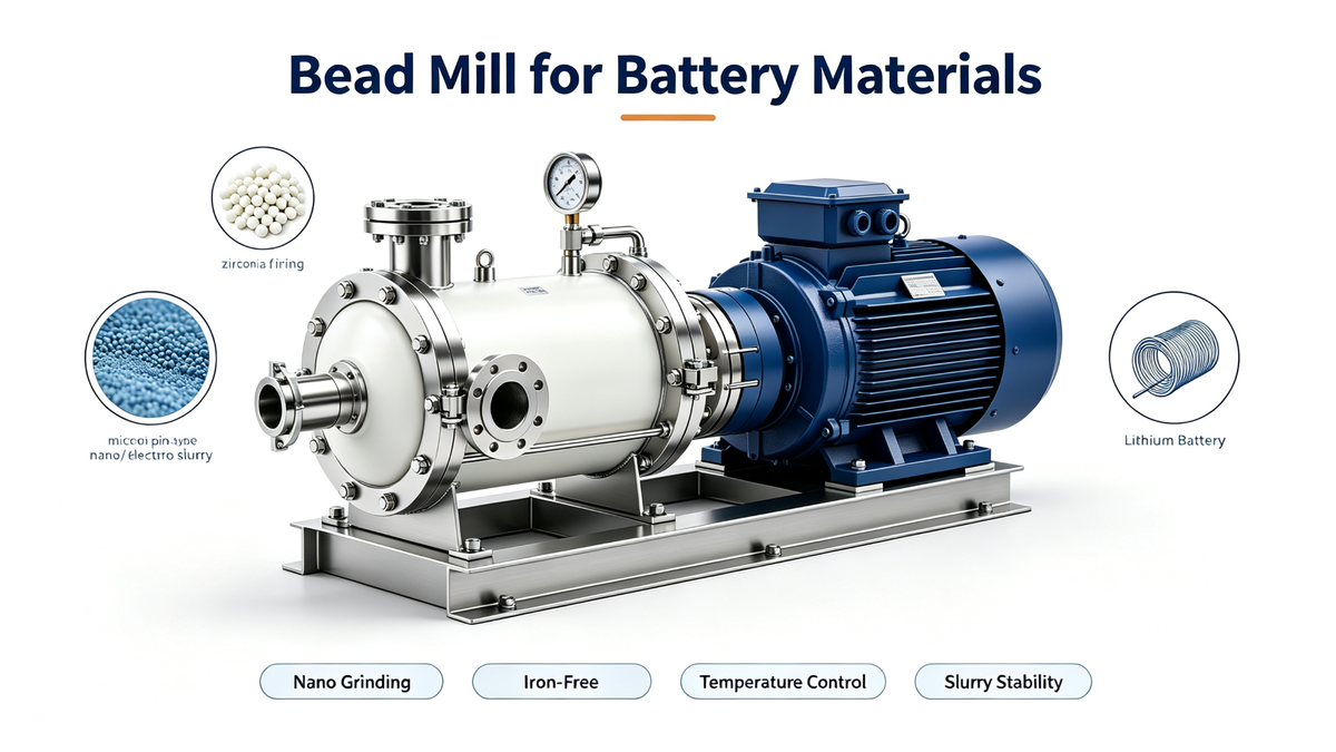
 Electrode slurry preparation has moved from a utility step to a performance-critical operation. Dispersion quality directly influences energy density, rate capability and cycle life, so the mill that produces excellent coatings pigment may still be entirely unsuitable for battery work if it introduces metallic contamination or fails to deagglomerate conductive additives.
Four criteria govern selection. Contamination control comes first, because trace iron, copper or nickel degrade cell performance. Dispersion quality follows, since carbon black and carbon nanotubes must be deagglomerated without destroying their structure. Thermal control matters because electrode slurries are temperature sensitive, and scale-up geometry reduces reformulation risk.
This article explains each criterion, sets out the configuration we recommend, and describes the verification and scale-up pathway that makes production predictable. It reflects 25 years of application engineering and the specific requirements of lithium-ion cathode, anode and conductive additive processing.
Electrode slurry preparation has moved from a utility step to a performance-critical operation. Dispersion quality directly influences energy density, rate capability and cycle life, so the mill that produces excellent coatings pigment may still be entirely unsuitable for battery work if it introduces metallic contamination or fails to deagglomerate conductive additives.
Four criteria govern selection. Contamination control comes first, because trace iron, copper or nickel degrade cell performance. Dispersion quality follows, since carbon black and carbon nanotubes must be deagglomerated without destroying their structure. Thermal control matters because electrode slurries are temperature sensitive, and scale-up geometry reduces reformulation risk.
This article explains each criterion, sets out the configuration we recommend, and describes the verification and scale-up pathway that makes production predictable. It reflects 25 years of application engineering and the specific requirements of lithium-ion cathode, anode and conductive additive processing.
Key Takeaways
- Contamination control comes first: ceramic-lined chambers, coated rotors and high-purity zirconia media
- Conductive additives must be deagglomerated without destroying their conductive network structure
- Thermal control stabilises viscosity, which improves coating consistency downstream
- Use the same mill geometry from laboratory through pilot to production to reduce reformulation risk
- Verify contamination limits by trial milling and analysis rather than assuming the configuration is sufficient
Criterion 1: Contamination Control
Trace metal contamination is the first selection criterion for battery work. Iron, copper and nickel ions from product-contact surfaces increase self-discharge and shorten cycle life, and the effect is measurable even at low concentrations. Contamination enters wherever product touches metal: the chamber, the agitator, the separator, seals, transfer piping and the media itself.
The control is to eliminate metallic contact in the grinding zone. Specify fully ceramic-lined chambers, ceramic or polymer-coated rotors, and high-purity yttria-stabilised zirconia media. Separator components, seals and downstream piping should be specified to the same standard, because contamination introduced after the mill is just as damaging as contamination inside it.
Verification completes the loop. Run a trial batch with the selected configuration and analyse it for magnetic and elemental impurities. Documenting the result gives production a baseline, so any change of media, wear part or supplier can be evaluated quickly rather than triggering full re-qualification.
Criterion 2: Nano Dispersion of Conductive Additives
Conductive additives determine how well an electrode conducts. Carbon black is the conventional choice and carbon nanotubes increasingly so, because they deliver conductivity at lower loading. Both are supplied as agglomerates that must be broken apart, and both are damaged by excessive shear, which shortens tube length and reduces the conductive network's effectiveness.
Nano bead mills with pin-type rotors and small zirconia media achieve the required deagglomeration. The endpoint is a balance rather than a minimum: enough energy to break agglomerates, not so much that the additive structure is destroyed. Establishing that balance requires measuring both particle distribution and a functional property such as slurry resistivity.
Because the window is narrow, specific energy and tip speed should be set from trials rather than run at maximum. Documenting the validated parameter set is essential, since electrode formulations are qualified slowly and expensively and reformulating after scale-up is costly.
Criterion 3: Thermal Control
Electrode slurries are temperature sensitive during milling. Heat changes viscosity, which changes energy transfer and therefore dispersion quality, so thermal drift appears as inconsistent slurry rather than as an obvious fault. Stable temperature is also closely linked to coating quality downstream, because coating weight depends on viscosity.
Production machines should therefore be specified with jacketed chambers, outlet temperature monitoring and interlocks to the feed rate, with recirculation cooling where thermal duty requires it. This allows the process to slow automatically if temperature rises, rather than relying on operator intervention after quality has already drifted.
Energy input should be set to the minimum that reaches specification. Excess energy becomes heat rather than finer dispersion, so the fastest setting is rarely the fastest route to a qualified slurry. Where the formulation is particularly sensitive, multi-pass operation with inter-pass cooling gives better control than a single high-energy pass.
Criterion 4: Scale-Up Geometry
Battery formulations are qualified slowly and expensively, so reformulating during scale-up is a significant cost and schedule risk. The most reliable mitigation is to keep mill geometry, media type and specific energy constant from laboratory through pilot to production, so results transfer without reformulation.
A three-stage pathway works well. Laboratory nano mills in the 0.5 to 10 litre range support formulation work and sample production. Pilot units of 30 to 100 litres validate the process at coating-relevant volume. Production machines from 200 litres per hour upward are then configured in multi-pass or multi-stage arrangements using the validated specific energy.
Choose a supplier able to provide the same geometry across all three stages, because this is what makes the pathway predictable. Documenting media charge, tip speed, feed rate, temperature limits and pass count during development gives production a validated starting parameter set rather than a search.
Recommended Configuration and Next Steps
The configuration we recommend for cathode, anode and conductive additive processing combines a fully ceramic-lined nano bead mill with a ceramic or polymer-coated pin-type rotor, high-purity zirconia media, ceramic-lined piping, jacketed cooling with outlet interlock, and a verification step based on trial milling with analysis.
Where the plant also handles binder solution and main slurry make-down, pair the mill with a double planetary mixer under vacuum so air is removed immediately before coating. This integration is standard in electrode slurry lines and avoids re-exposing deaerated slurry to atmosphere.
To move forward, send your chemistry, target particle size, solids content, contamination limits and required throughput through the inquiry form. Our engineers will configure a contamination-controlled milling solution around your specification and provide laboratory, pilot and production machines sharing the same geometry.
Technical Specifications
| Chamber lining | fully ceramic-lined for contamination control |
| Rotor | ceramic or polymer-coated pin type |
| Media | high-purity yttria-stabilised zirconia, typically 0.05 - 0.8 mm |
| Fineness | sub-100 nm to 2 micron depending on material |
| Cooling | jacketed chamber with outlet temperature interlock and optional recirculation cooling |
| Scale-up path | laboratory 0.5 - 10 L, pilot 30 - 100 L, production from 200 L/h |
Troubleshooting Guide
Slurry fails magnetic impurity limits
Cause: Metallic contact from chamber, rotor, separator, seals or media
Solution: Specify fully ceramic-lined chamber with coated rotor and high-purity zirconia media, then verify by trial milling and analysis
Conductivity is lower than expected after dispersion
Cause: Excessive shear shortening carbon nanotubes and damaging the conductive network
Solution: Set specific energy and tip speed from trials and measure slurry resistivity alongside particle distribution
Slurry viscosity drifts during production
Cause: Thermal drift changing rheology and energy transfer
Solution: Verify jacketed cooling capacity, monitor outlet temperature and interlock to feed rate
Production results differ from laboratory qualification
Cause: Different mill geometry, media or specific energy between development and production
Solution: Use the same geometry across laboratory, pilot and production and hold media type and specific energy constant
Frequently Asked Questions
Why is a standard bead mill unsuitable for battery slurry?
Because stainless contact surfaces release iron, chromium and nickel under high shear, and those ions degrade cell performance. Battery work requires fully ceramic-lined chambers, coated rotors and high-purity zirconia media, plus verification by analysis rather than assumption.
What contamination limits should I expect?
Limits are set by you and differ by chemistry and cell design, so they should be stated when specifying equipment. The practical approach is to configure for the lowest contamination achievable and verify by trial milling with analysis, documenting the result as a baseline.
How do I disperse carbon nanotubes without damaging them?
Use a nano bead mill with pin-type rotor and small zirconia media, and set specific energy from trials rather than running at maximum. Verify by measuring both particle distribution and slurry resistivity, since resistivity reveals whether the conductive network survived.
Do I need a separate mixer as well as a mill?
Usually yes. A double planetary mixer handles binder solution and main slurry make-down, while the mill disperses conductive additives. Pairing them with vacuum deaeration before coating is the standard configuration for electrode slurry lines.
How important is cooling for battery slurry?
Very. Temperature affects viscosity, which affects both dispersion quality and coating consistency downstream. Specify jacketed chambers with outlet monitoring and interlocks, and set energy input to the minimum that reaches specification.
Can I scale from laboratory directly to production?
It is possible but risky for battery formulations, which are expensive to re-qualify. A pilot stage at 30 to 100 litres validates thermal behaviour and throughput before production sizing, and using the same geometry throughout makes transfer predictable.
What should I include in an inquiry for battery milling?
Include the chemistry, target particle size, solids content, contamination limits, required throughput, available utilities and destination country. With that information we can configure a contamination-controlled solution and quote laboratory, pilot and production machines with shared geometry.
Recommended POLYC MACHINE equipment
The following machines are commonly evaluated for the process described above. Final selection depends on formulation, target particle size, viscosity, capacity and contamination limits.
Related technical guides
Next step
Share your material, required capacity, target fineness and operating conditions with POLYC MACHINE engineers for a configuration review and quotation.
Explore our Fine Chemicals solutions for application-specific equipment configurations and process recommendations.